
Screamin' Eagle 4.000 Inch High Compression Piston Kits
J042412009-05-21
GENERAL
Kit Number
22502-07, 22501-07, and 22503-07
Models
For model fitment information, see the P&A Retail Catalog or the Parts and Accessories section of www.harley-davidson.com (English only).
Additional Parts Required
NOTICE
You must recalibrate the ECM when installing this kit. Failure to properly recalibrate the ECM can result in severe engine damage. (00399b)
NOTE
ECM recalibration is required, which can be performed with the Screamin' Eagle Race Tuner Kit (part number 32107-01F). See a Harley-Davidson Dealer.
 WARNING
Rider and passenger safety depend upon the correct installation of this kit. Use the appropriate service manual procedures. If the procedure is not within your capabilities or you do not have the correct tools, have a Harley-Davidson dealer perform the installation. Improper installation of this kit could result in death or serious injury. (00333b)
NOTE
This instruction sheet references service manual information. A service manual for your model motorcycle is required for this installation and is available from a Harley-Davidson dealer.
Kit Contents

Figure 1. Piston Kits
Table 1. Piston Kits
Kit Number | Description |
|---|---|
22502-07 | Piston Kit, Standard |
22501-07 | Piston Kit, +0.005 in. |
22503-07 | Piston Kit, +0.010 in. |
This engine related performance part is intended for high performance or racing applications. and is not legal for sale or use on pollution controlled motor vehicles. This kit will reduce or void the limited vehicle warranty. Engine related performance parts are intended for the experienced rider only..
PREPARE FOR SERVICE
| 1. | Position motorcycle on a suitable lift. NOTE If vehicle is equipped with Harley-Davidson Smart Security System, see owner's manual for instructions to disarm the system. | |
| 2. | Remove seat according to the instructions in the service manual. | |
| WARNING To prevent accidental vehicle start-up, which could cause death or serious injury, disconnect battery cables (negative (-) cable first) before proceeding. (00307a) WARNINGDisconnect negative (-) battery cable first. If positive (+) cable should contact ground with negative (-) cable connected, the resulting sparks can cause a battery explosion, which could result in death or serious injury. (00049a) WARNINGWhen servicing the fuel system, do not smoke or allow open flame or sparks in the vicinity. Gasoline is extremely flammable and highly explosive, which could result in death or serious injury. (00330a) | ||
| 3. | Touring: Remove left side saddlebag, left side cover, and main fuse. Refer to the service manual. Softail: Remove main fuse. Refer to the service manual. Dyna: Remove electrical caddy cover and main fuse. Refer to the service manual. |
INSTALLATION
| 1. | Refer to the service manual and follow the instructions given to remove the seat and disconnect the battery cables, negative cable first. | |
| 2. | Refer to the appropriate sections of the service manual for cylinder head, cylinder and piston removal procedures. | |
| 3. | Follow the procedures in the service manual for inspection of parts. | 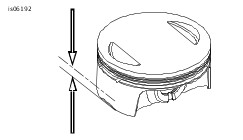 Figure 2. 0.394 in. (10 mm) |
Measuring Pistons
- Allow the piston to cool to room temperature.
- With a pencil or marker, mark the piston on each side of the skirt across the thrust faces (perpendicular to the piston pin bore) 0.394 inch (10 mm) from the bottom edge.
- Using a micrometer at the marks, measure the nominal diameter of the piston.
- Use a dial bore gauge to measure the piston ring travel zone in the cylinder bore.
- Bore and hone cylinders as needed to achieve piston fit in Table 2. Refer to the service manual.
NOTE
Set the piston skirt down on a level table and use a rule to measure 0.394 inch (10 mm) high on the skirt.
NOTE
For cylinder bore measurement refer to the appropriate section in the service manual.
Installing Pistons
| 4. | The pistons in this kit are front and rear cylinder specific. The pistons may be marked with "FRONT" and "REAR" text or they may have a number on top. Refer to the table below to determine the front and rear piston if they do not have the text marking on top pointing towards the front of the engine. NOTE Install rings with dots or bevels facing up. Rings with no markings can be installed either side up. 4.000 inch cylinders do not use O-rings (part number 11273) on the top cylinder dowels. Therefore, do not install them when using torque plates or at final assembly of engine. Re-jetting and/or re-timing of engine may be required to realize the full potential of this high performance product. High compression piston applications require installation of appropriate compression release in the cylinder heads of they are not already equipped. Always check piston-to-valve clearance with non-stock camshafts. |
Table 2. Piston Identification
Size | Front Piston Number | Rear Piston Number |
|---|---|---|
Standard | 22504-07 | 22527-07 |
+.005 in. | 22532-07 | 22554-07 |
+.010 in. | 22555-07 | 22556-07 |
Table 3. Piston Specifications
ITEM | IN. | MM |
|---|---|---|
Fit in Cylinder | 0.0018-0.0027 | 0.046-0.069 |
Top Ring End Gap 2nd Ring End Gap Oil Control Ring Rail | 0.016-0.024 0.014-0.022 0.010-0.030 | 0.406-0.610 0.356-0.559 0.254-0.762 |
Top Ring Side Clearance 2nd Ring Side Clearance | 0.00098-0.0024 0.00098-0.0024 | 0.025-0.061 0.025-0.061 |
Piston Pin Fit (Loose) | 0.0005-0.0009 | 0.013-0.023 |
Table 4. Service Wear Limits
ITEM | IN. | MM |
|---|---|---|
Fit in Cylinder (Loose) | 0.003 | 0.076 |
Piston Pin Fit (Loose) | 0.0009 | 0.023 |
Top Ring End Cap 2nd Ring End Cap Oil Control Ring Rail | 0.034 0.032 0.030 | 0.864 0.813 0.762 |
Top Ring Side Clearance 2nd Ring Side Clearance Oil Control Ring Rail | 0.0032 0.0032 0.004 | 0.081 0.081 0.102 |
Piston Pin Circlip Installation
| 5. | See Figure 3. Insert open end of circlip (1) into notch (2) on groove (3). | |||||||||||
| 6. | See Figure 4. Place thumb on piston (1) and press firmly until approximately 85% of circlip (2) is seated in groove. | |||||||||||
| 7. | Use a small blade screwdriver to wedge circlip into remainder of groove, being careful not to scratch or mar piston. Repeat for remaining circlips. NOTE Make sure the circlip is fully seated for proper installation. | 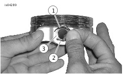
Figure 3. Circlip and Piston 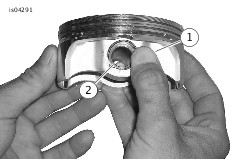
Figure 4. Install Circlip | ||||||||||
| 8. | Install cylinder heads cylinders, and high compression pistons and rings from kit. Refer to appropriate sections in service manual. |
FINAL ASSEMBLY
| 1. | Install fuel tank according to the instructions in the service manual. | |
| 2. | Touring: Install main fuse, left side cover, and left side saddlebag. Refer to the service manual. Softail: Install main fuse. Refer to the service manual. Dyna: Install main fuse and electrical caddy cover. Refer to the service manual. | |
| WARNING After installing seat, pull upward on seat to be sure it is locked in position. While riding, a loose seat can shift causing loss of control, which could result in death or serious injury. (00070b) | ||
| 3. | Install seat according to the instructions in the service manual. |
BREAK-IN RIDING RULES
Refer to the Owner's Manual for instructions to break-in the motorcycle.
SERVICE PARTS
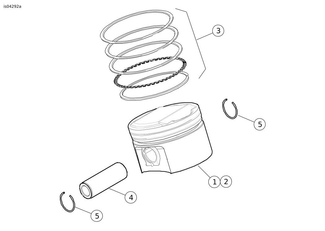
Figure 5. Service Parts: Screamin' Eagle 4.000 Inch High Compression Piston Kits
Table 5. Service Parts: Screamin' Eagle 4.000 Inch High Compression Piston Kits
Kit | Item | Description (Quantity) | Part Number |
|---|---|---|---|
Kit 22502-07 Standard | 1 | Piston, front, standard | Not Sold Separately |
2 | Piston, rear, standard | Not Sold Separately | |
3 | Piston Ring Set, standard (2) | 22285-07 | |
4 | Pin, piston (2) | 22558-07 | |
5 | Circlip, piston pin (4) | 22097-99 | |
Kit 22502-07 +0.005 Inch | 1 | Piston, front, +.005 inch | Not Sold Separately |
2 | Piston, rear, +.005 inch | Not Sold Separately | |
3 | Piston Ring Set, +.005 inch (2) | 22286-07 | |
4 | Pin, piston, (2) | 22558-07 | |
5 | Circlip, piston pin (4) | 22097-99 | |
Kit 22503-07 +0.010 Inch | 1 | Piston, front, +.010 inch | Not Sold Separately |
2 | Piston, rear, +.010 inch | Not Sold Separately | |
3 | Piston Ring Set, +.010 inch (2) | 22287-07 | |
4 | Pin, piston (2) | 22558-07 | |
5 | Circlip, piston pin (4) | 22097-99 |