NOTE
Do not overtighten shock absorber adjusters. Overtightening could result in damage to shock absorbers.
Preload Adjustment
Adjust the shock absorber preload for the total weight the motorcycle is to carry.
- Increase the preload to accommodate more weight.
- Reduce the preload if carrying less weight.
Suspension preload is set via two preload adjusters:
Threaded Preload Adjuster (Right Shock Absorber): Used to set the suspension preload for the primary loading condition. This includes:
- Rider only
- Rider + Passenger
- Rider + Tour-Pak
- Rider + Passenger + Tour-Pak
Remote Hydraulic Preload Adjuster (Left Shock Absorber): Used to set the suspension preload for an additional 45 kg (100 lb) of cargo loading. Additionally, the hydraulic preload adjuster can also be used for short term passenger adjustments with minimal cargo.
Set threaded preload adjuster for the primary loading condition (Rider/Passenger/Tour-Pak).
| 1. | Remove the right saddlebag. See Operation → SADDLEBAGS. | |
| 2. | Determine the primary loading condition that the vehicle will most often be used in (Rider Only, Rider + Passenger, Rider + Tour-Pak or Rider + Passenger + Tour-Pak). | |
| 3. | Use Table 1 to calculate preload distance for the threaded preload adjuster for primary loading condition. | |
| 4. | For vehicles with a Tour-Pak, add a preload distance to the calculated primary loading condition preload setting. Length/Dimension/Distance: 15 mm (0.59 in) | |
| 5. | See Figure 1. Using the provided spanner wrench, turn the lock ring (1) on right shock counterclockwise (CCW) to minimum (MIN). | |
| 6. | Turn the adjustment ring (2) clockwise (CW) until the distance from the top of the adjustment ring to the bottom of the lock ring (in mm) matches the calculated preload distance determined in steps 3 and 4, above. | |
| 7. | Holding adjustment ring in place, turn lock ring CW and tighten against adjustment ring using the spanner wrench. | |
| 8. | Install the right saddlebag. See Operation → SADDLEBAGS. |
Set preload for cargo weight.
| 1. | Determine the weight of all cargo. | |
| 2. | See Figure 2. Turn the remote hydraulic adjustment knob (2) on the left shock fully CCW to MIN. | |
| 3. | Refer to Table 2. Turn the remote hydraulic adjustment knob CW the number of full turns listed in the table for that cargo weight. |
NOTE
The remote hydraulic preload adjuster can be used for short term passenger adjustments with minimal cargo. Turn the hydraulic adjustment knob CW to maximum (MAX) when the passenger is on the vehicle.
Perform damping adjustment. Proceed to Damping Adjustment.
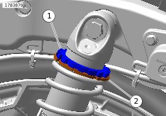
| 1 | Lock ring |
| 2 | Adjustment ring |
Figure 1. Threaded Adjuster (Right Side Shock Absorber)
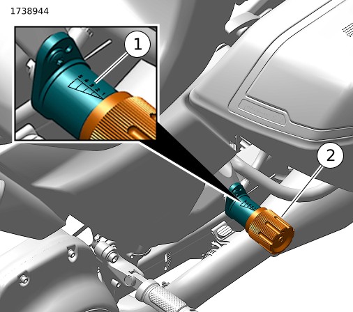
| 1 | Preload scale |
| 2 | Hydraulic adjustment knob |
Figure 2. Hydraulic Preload Adjustment Knob (Left Side Shock Absorber)
Table 1. Right Shock Absorber Threaded Preload Adjuster Settings for Rider/Passenger
ADDITIONAL WEIGHT OF PASSENGER | |||||||||||||||||||||
|---|---|---|---|---|---|---|---|---|---|---|---|---|---|---|---|---|---|---|---|---|---|
LB | 0 | 10 | 20 | 30 | 40 | 50 | 60 | 70 | 80 | 90 | 100 | 110 | 120 | 130 | 140 | 150 | 160 | 170 | 180 | ||
KG | 0 | 5 | 9 | 14 | 18 | 23 | 27 | 32 | 36 | 41 | 45 | 50 | 54 | 59 | 64 | 68 | 73 | 77 | 82 | ||
RIDER WEIGHT | |||||||||||||||||||||
LB | KG | mm Between Top of Adjuster Ring and Bottom of Lock Ring | |||||||||||||||||||
150 | 68 | 0 | 4 | 9 | 13 | 17 | 21 | 26 | 30 | 34 | 38 | 43 | 47 | 51 | 56 | 60 | 61 | 61 | 61 | 61 | |
160 | 73 | 0 | 4 | 9 | 13 | 17 | 21 | 26 | 30 | 34 | 38 | 43 | 47 | 51 | 56 | 60 | 61 | 61 | 61 | 61 | |
170 | 77 | 0 | 4 | 9 | 13 | 17 | 21 | 26 | 30 | 34 | 38 | 43 | 47 | 51 | 56 | 60 | 61 | 61 | 61 | 61 | |
180 | 82 | 0 | 4 | 9 | 13 | 17 | 21 | 26 | 30 | 34 | 38 | 43 | 47 | 51 | 56 | 60 | 61 | 61 | 61 | 61 | |
190 | 86 | 3 | 7 | 12 | 16 | 20 | 24 | 29 | 33 | 37 | 42 | 46 | 50 | 54 | 59 | 61 | 61 | 61 | 61 | 61 | |
200 | 91 | 6 | 10 | 15 | 19 | 23 | 28 | 32 | 36 | 40 | 45 | 49 | 53 | 58 | 61 | 61 | 61 | 61 | 61 | 61 | |
210 | 95 | 9 | 14 | 18 | 22 | 26 | 31 | 35 | 39 | 44 | 48 | 52 | 56 | 61 | 61 | 61 | 61 | 61 | 61 | 61 | |
220 | 100 | 12 | 17 | 21 | 25 | 30 | 34 | 38 | 42 | 47 | 51 | 55 | 59 | 61 | 61 | 61 | 61 | 61 | 61 | 61 | |
230 | 104 | 16 | 20 | 24 | 28 | 33 | 37 | 41 | 45 | 50 | 54 | 58 | 61 | 61 | 61 | 61 | 61 | 61 | 61 | 61 | |
240 | 109 | 19 | 23 | 27 | 31 | 36 | 40 | 44 | 49 | 53 | 57 | 61 | 61 | 61 | 61 | 61 | 61 | 61 | 61 | 61 | |
250 | 113 | 22 | 26 | 30 | 35 | 39 | 43 | 47 | 52 | 56 | 60 | 61 | 61 | 61 | 61 | 61 | 61 | 61 | 61 | 61 | |
260 | 118 | 25 | 29 | 33 | 38 | 42 | 46 | 51 | 55 | 59 | 61 | 61 | 61 | 61 | 61 | 61 | 61 | 61 | 61 | 61 | |
270 | 122 | 28 | 32 | 37 | 41 | 45 | 49 | 54 | 58 | 61 | 61 | 61 | 61 | 61 | 61 | 61 | 61 | 61 | 61 | 61 | |
Table 2. Left Shock Absorber Hydraulic Preload Adjuster Settings for Cargo
CARGO WEIGHT | Turns from MIN | |
|---|---|---|
LB | KG | |
0 | 0 | 0 |
10 | 5 | 1 |
20 | 9 | 3 |
30 | 14 | 4 |
40 | 18 | 5 |
50 | 23 | 7 |
60 | 27 | 8 |
70 | 32 | 9 |
80 | 36 | 11 |
90 | 41 | 12 |
100 | 45 | 13 |
110 | 50 | 15 |
120 | 54 | 16 |
130 | 59 | 17 |
140 | 64 | 19 |
150 | 68 | 20 |
160 | 73 | 20 |
170 | 77 | 20 |
180 | 82 | 20 |
Damping Adjustment
Both shock absorbers have damping adjusters to obtain ideal suspension performance across a range of loading conditions. The damping adjusters should be set to the recommended setting when rear suspension preload is adjusted, and both should be set to the same setting.
- Increase the damping adjuster setting for increased Rider/Passenger/Cargo weight or a stiffer ride.
- Reduce the damping adjuster setting for decreased Rider/Passenger/Cargo weight or a softer ride.
| 1. | Remove saddlebags. See Operation → SADDLEBAGS. | |
| 2. | See Figure 3. Turn the damping adjustment thumbwheels on both shock absorbers in the H (hard) direction until the adjuster stops, then turn one click in the S (soft) direction. | |
| 3. | Set damping adjustment for Rider/Cargo/Passenger/Tour-Pak weight. a. Determine the weight of the rider and cargo. Refer to Table 3 to calculate the damping adjuster position (clicks toward S (soft) from the MAX H (hard) position). b. For vehicles with a Tour-Pak, subtract 3 clicks from the calculated Rider/Cargo damping adjuster setting. c. For vehicles with a passenger, set the damping adjustment thumbwheels on both shock absorbers in the MAX H (hard) position. d. Turn the damping adjustment thumbwheels the number of clicks in the S (soft) direction calculated from steps 3-a through 3-c, above. | |
| 4. | Install saddlebags. See Operation → SADDLEBAGS. |
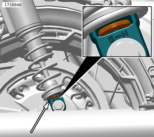
Figure 3. Damping Adjustment Thumbwheel (Both Shock Absorbers)
Table 3. Damping Adjustment Setting for Rider/Cargo
ADDITIONAL WEIGHT OF CARGO/ACCESSORIES | |||||||||||
|---|---|---|---|---|---|---|---|---|---|---|---|
LB | 0 | 10 | 20 | 30 | 40 | 50 | 60 | 70 | 80 | ||
KG | 0 | 5 | 9 | 14 | 18 | 23 | 27 | 32 | 36 | ||
RIDER WEIGHT | |||||||||||
LB | KG | Clicks from MAX | |||||||||
150 | 68 | 10 | 10 | 9 | 8 | 7 | 6 | 6 | 5 | 4 | |
160 | 73 | 9 | 9 | 8 | 7 | 6 | 5 | 5 | 4 | 3 | |
170 | 77 | 8 | 8 | 7 | 6 | 5 | 4 | 4 | 3 | 2 | |
180 | 82 | 8 | 8 | 7 | 6 | 5 | 4 | 4 | 3 | 2 | |
190 | 86 | 8 | 8 | 6 | 6 | 5 | 4 | 3 | 3 | 2 | |
200 | 91 | 7 | 7 | 6 | 5 | 4 | 3 | 3 | 2 | 2 | |
210 | 95 | 7 | 7 | 6 | 5 | 4 | 3 | 3 | 2 | 1 | |
220 | 100 | 7 | 7 | 5 | 5 | 4 | 3 | 2 | 2 | 1 | |
230 | 104 | 6 | 6 | 5 | 4 | 3 | 2 | 2 | 1 | 1 | |
240 | 109 | 6 | 6 | 5 | 4 | 3 | 2 | 2 | 1 | 0 | |
250 | 113 | 6 | 6 | 4 | 4 | 3 | 2 | 1 | 1 | 0 | |
260 | 118 | 5 | 5 | 4 | 3 | 2 | 1 | 1 | 0 | 0 | |
270 | 122 | 5 | 5 | 4 | 3 | 2 | 1 | 1 | 0 | 0 | |
280 | 126 | 5 | 5 | 3 | 3 | 2 | 1 | 0 | 0 | 0 | |
290 | 130 | 4 | 4 | 3 | 2 | 1 | 0 | 0 | 0 | 0 | |